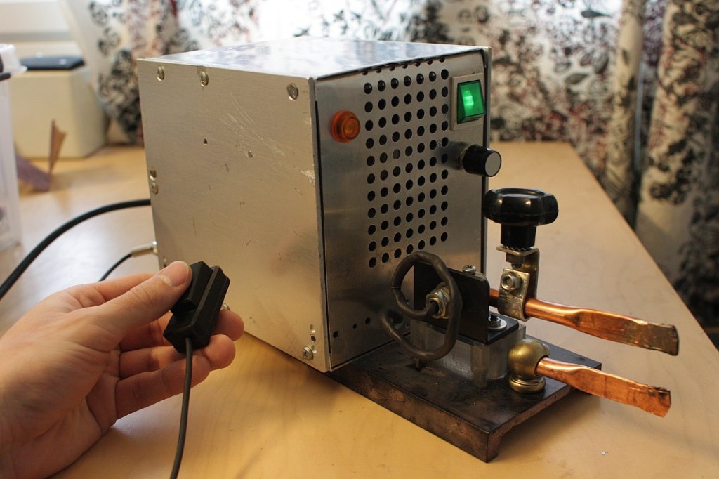
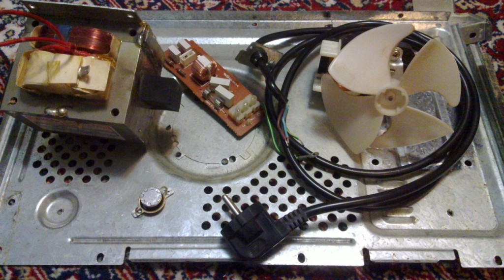
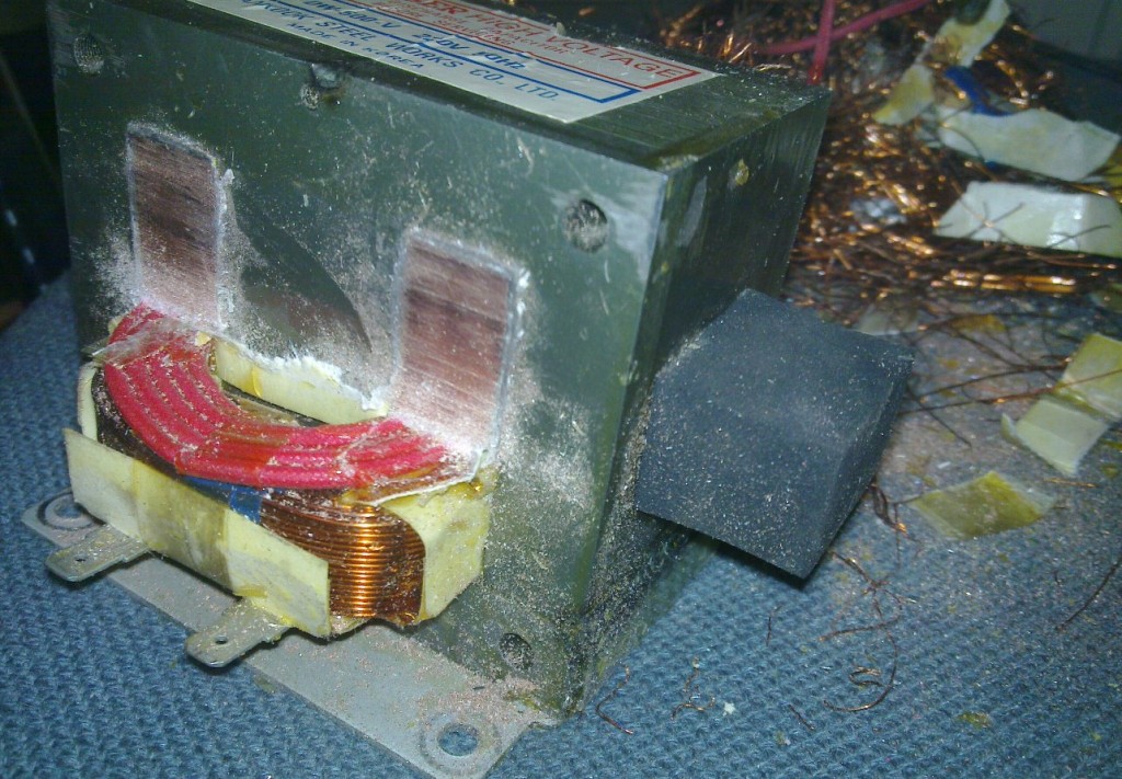
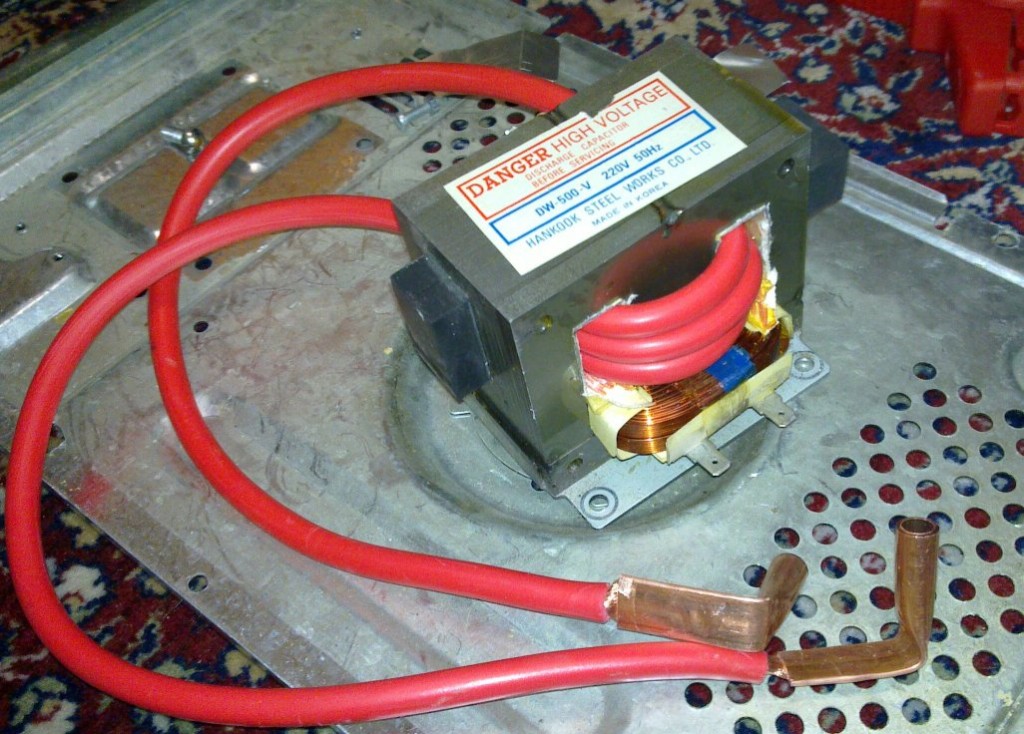
I made a spot welder out of a microwave oven transformer and a starter cable. Those are quite popular actually. They use a solid state relay to switch the transformer on and off. I use a Fotek SSR-40DA DC-controlled 40 A AC-zero-crossing-switching solid state relay. It was only 4 € and free shipping on eBay. First I needed to extract the transformer from a microwave oven and to replace the secondary coil with a starter cable.

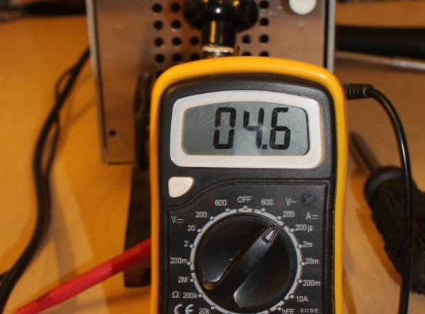
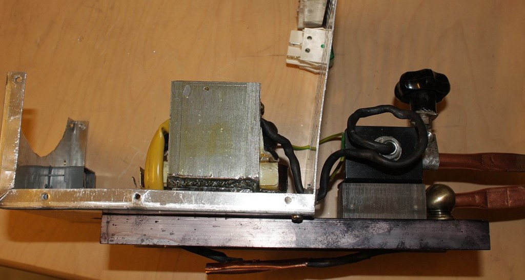

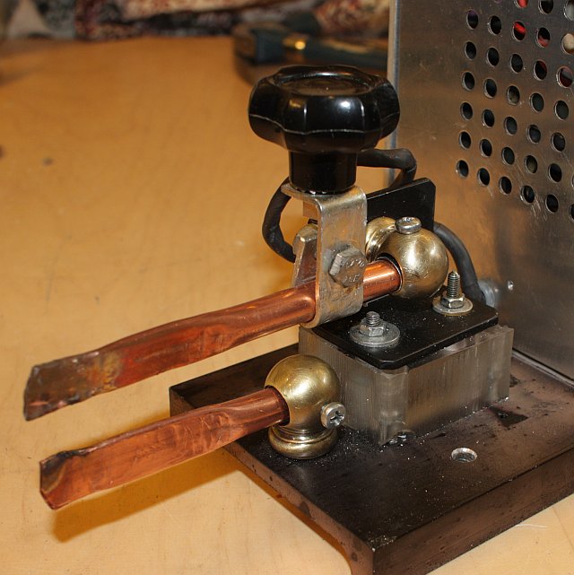
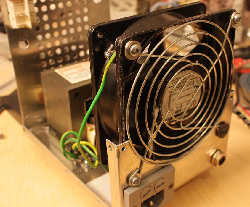
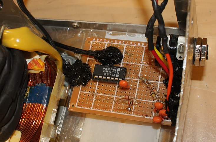
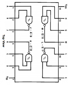
I wanted to automate the welding timing so I made this simple adjustable-duration pulse generator circuit out of some components that I had around:
|
|
Parts list:
- Resistor 1 kohm (R4)
- Resistor 9 kohm (R1)
- Resistor 40 kohm (R2)
- Multi-turn or log taper pot 10 kohm (VR1)
- 3x Capacitor 10 V 10 uF (you can put the extra capacitor in parallel with C2 to make the pulse longer if needed) (C1, C2)
- CD4093BC Quad two-input NAND Schmitt trigger logic gate
The variable resistor VR1 controls the timing. I used a helical potentiometer but a log pot would probably work just as well. The higher resolution is needed for long welding pulse times for which the whisker of VR1 is close to R2. R1 and R2 adjust the range of the voltage divider. Capacitor C2 is also charged through R1. The voltage divider range should be such that at one extreme, continuous welding is just barely enabled (by keeping the button pressed), and the other extreme just barely gives the shortest welding time that may be needed. If the obtainable shortest welding times are unnecessarily long, the capacitor C2 can be made larger. This will make it easier to get also very long pulse times. Doubling the capacitance should double the timing.
A rough approximation on how the voltage across C2 rises after the button is depressed at time $t = 0$ is given by:
$V_{\text{C2}}= \frac{5\text{V}\cdot t\cdot(R_{\text{R2}} + R_{\text{VR1}})}{C_{\text{C2}}\cdot R_{\text{R1}}\cdot(R_{\text{R2}} + R_{\text{VR1}}) + t\cdot(R_{\text{R1}} + R_{\text{R2}} + R_{\text{VR1}})}$
where $R$ is resistance and $C$ is capacitance across a component. $R_{\text{VR1}}$ is the nominal resistance of the variable resistor, not the current set value. The first half of the variable resistor VR1 and the second half of the variable resistor VR1 + resistor R2 act as a voltage divider that feeds a divided $V_{\text{C2}}$ to a Schmitt trigger which will trigger at nominally 3.3 V, ending the pulse.

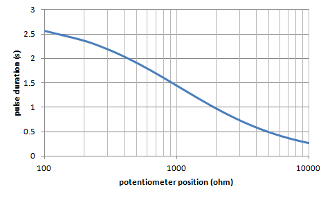
An initial version of the circuit took about a second to recover before it was able to produce another pulse after releasing the button. Resistor R4 was added to remedy this. It quickly drains the capacitors empty when the button disconnects the circuit from the power supply.
The circuit is fail-safe in the sense that it only gets power through the button. If the button is released, the output soon goes down, even if the IC or anything else in the circuit malfunctions for some reason. I use this circuit to control (the LED + series resistor of) an optically isolating solid state relay directly.
Noise can be a problem at longer pulse durations, where a sudden spike may end the welding pulse prematurely.
The timer is not synchronized to AC, so timing will also vary if the solid state relay is of the zero-crossing switching type.
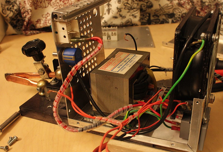
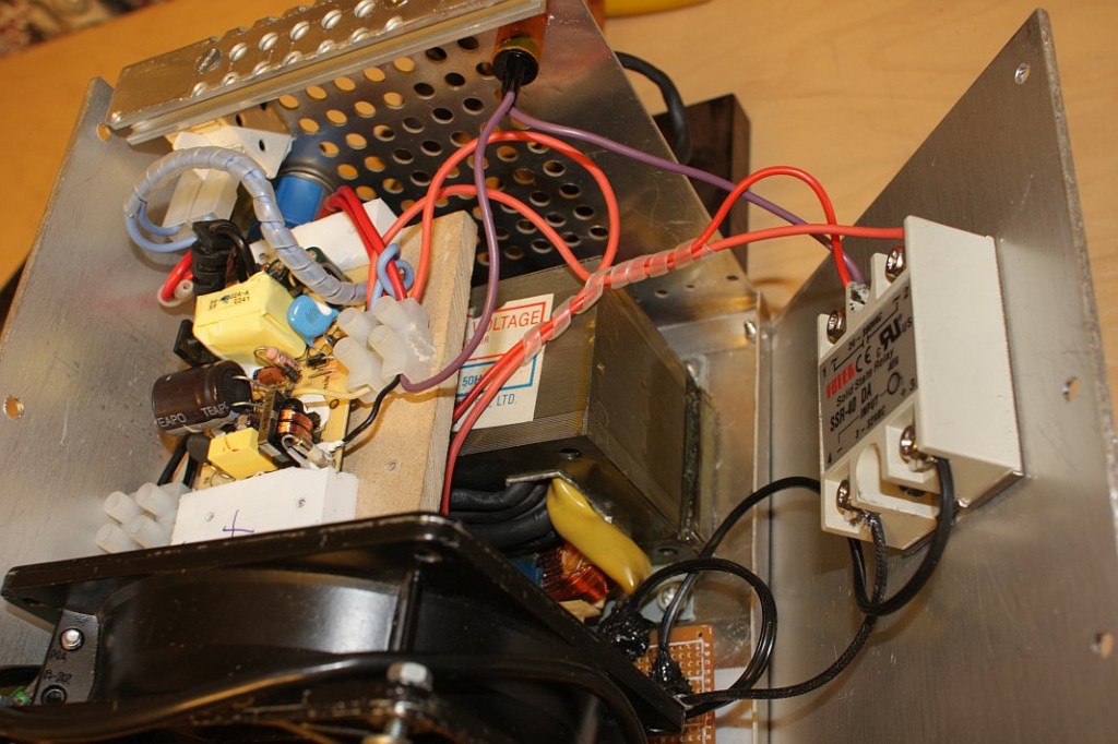

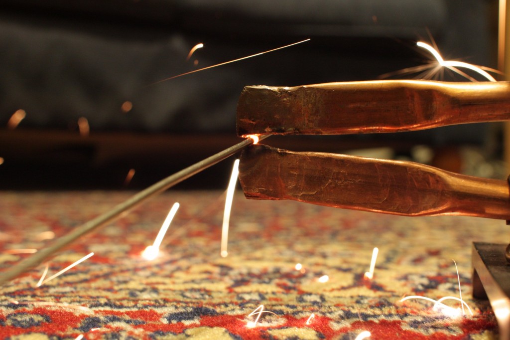
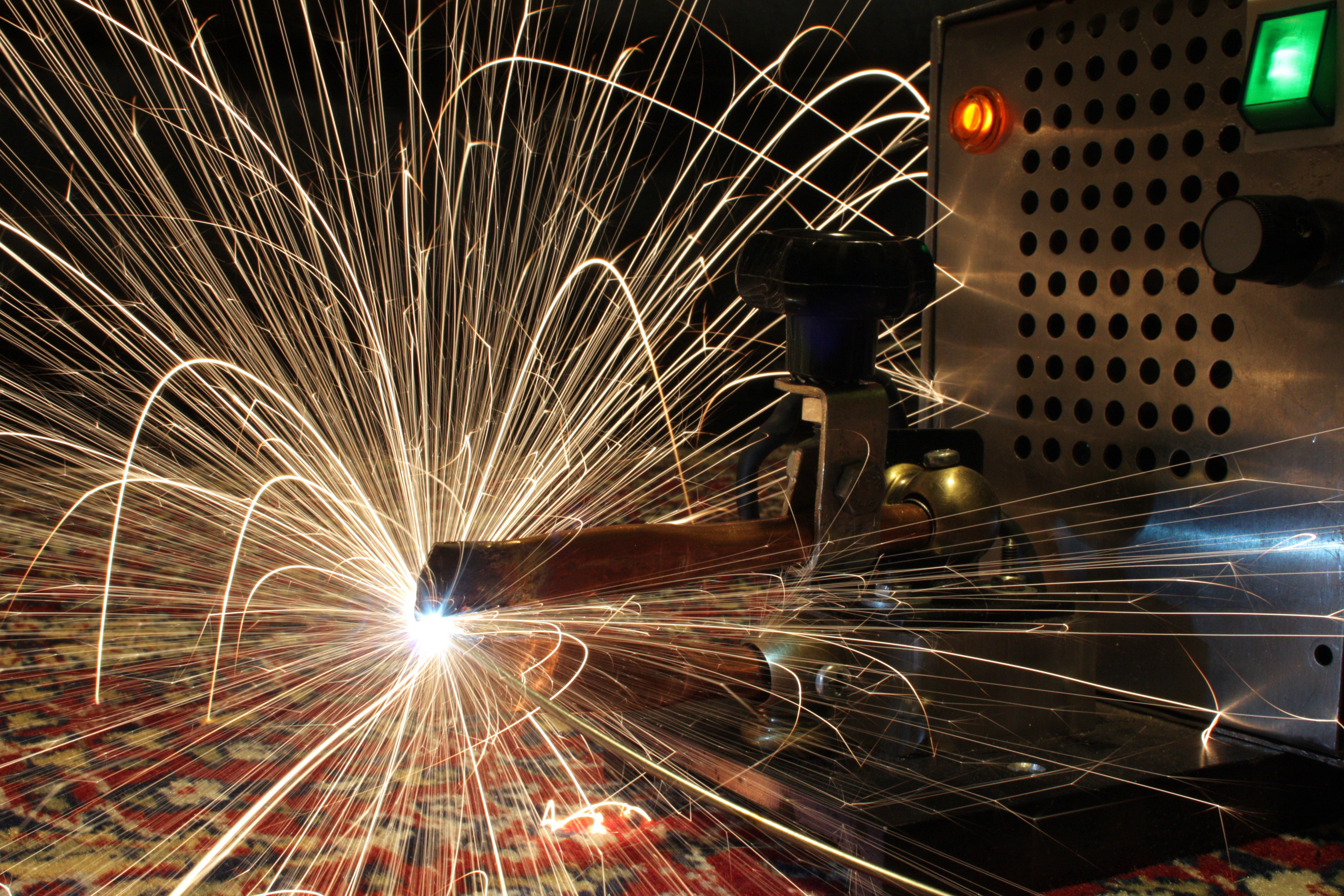
Welding results are mediocre at best. But strong enough for some purposes. One problem is that when the workpiece starts to melt, the current increases dramatically, causing a small "explosion". I am not sure how this could be improved upon to give a steady current.
Could you somehow measure the current, and using that reading, feed it into a micro using the PID algorithm (http://en.wikipedia.org/wiki/PID_controller) to control the SSD. I’m using a thermocouple in a toaster oven with an atmega running a PID loop to (roughly) follow a reflow curve for surface mount soldering. If you want code, you can’t have it as it doesn’t currently exist; I’m in the process of writing it and developing the project! Plenty of others have done the same. I’d recommend Beauregard’s post on his implementation of the PID algorithm for Arduino: http://brettbeauregard.com/blog/2011/04/improving-the-beginners-pid-introduction/
Very cool, thanks for posting.
Will: I’ve been thinking the same. Perhaps the current could be measured from acoustic emissions, or inductively from the secondary coil. The SSD is zero-crossing switching so the control will be rather coarse. Perhaps automatic pulse stopping would be enough.
“One problem is that when the workpiece starts to melt, the current increases dramatically, causing a small “explosion”. I am not sure how this could be improved upon to give a steady current.”
I’m no expert but I’d say that’s what it should do-
For welding a round rod as in the photo your timing would be critical so as not to melt it, welding two flat sheets would be a bit easier. But you still may need some means to get the right pressure on the tips. Otherwise looks good.
You do see portable commercial spot welders with no timing circuit at all and you just release the trigger at the right time to get a good weld, the timing circuit would be handy if you had a lot of similar welds to make. The commercial units are however set up so as to get some serious pressure on the tips.
Thanks for the posting, lots for us would/wanna bees to learn from it.
Thanks Oldie, that makes sense. For welding round pieces, if there is enough constant pressure, then the molten metal should flow out of the gap and not heat up too much, given that you will end the pulse in time. Probably more pressure is needed when welding plates together, as it will be more difficult to get a good contact with those. But maybe I could add a very small toroidal transformer around the fat secondary cable to sense the current that goes through the workpiece. Would be interesting to graph that at least, to see if it perhaps tells something about what’s happening.
To measure current into a micro controller like arduino, take a torroid ring core that will fit over an output wire, cut a small section out of the torriod and place a Hall effect sensor in there, measure the magnetic force produced if you know what I mean
Like this
http://www.machsupport.com/forum/index.php/topic,10339.60.html
One thing that would prevent “explosions” is a purge gas like CO2. It would be a better weld too.
Thanks Mike, that would be a nice addition.
The sparks are caused by resistance between the copper tip and the metal rapidly heating that area causing expulsions.
Melted copper tips and flying molten metal is not due to too many amps.
Get heavy duty copper for tips and clamp down securely with 70 – 120 kg pressure before welding.
Commercial auto spot welders can put 50,000 amps through their tip and you don’t even see the area glowing.
They use mega amps, short time periods and clamping pressure. The spot of melting in a spot weld should be between the two plates or whatever you join, not on the surface between copper tip and plate.
Anyhoo my point is you don’t have too much current.
Regards doug..
Just another comment for anyone looking at making a spot welder.
You want the most resistance in your circuit to be at the point between the two plates. That way the heat builds up their first and the molten nugget forms on in inside. Everything good but too little time will give an improperly formed small nugget which is weak. Just the right time will give an ideal sized strong nugget. More time after that does not increase the size of the nugget but starts to be detrimental weakening spot weld.
Size of spot weld tip diameter in contact should be plate thickness + other plate thickness + 3.4mm
So for 2 x 1mm plate a tip that gives a 5.4mm spot weld is ideal. A shallow domed curve is ideal as it assists with pressure initially and broadens quickly, this gives a larger diameter and less pressure towards the end of the spot weld.
Regards Doug.
Nice project and quiet dangerously,……
Hi folks, having recently acquired a commercial, “hand-held” (bloody heavy) spot welder WITHOUT any timers or any electronic additions I can say the following:
1) Electronic timers are NOT a requirement for a few incidental welds -just a bit of experience will do.
2) Clamping pressure is vital -you need a LOT of it. (that plus decently clean surfaces; rust / oxidation tends to be a problem due to the low voltage.)
I fully endorse Dough’s comment; he knows well what it’s about.
You guys are so right, I need more pressure. I just tried a large-ish spot welder and had a hard time on applying enough pressure on the pedal to operate it. It made good welds without a timer.
What output voltage on pin 4 its if input voltage its 5V. In my case its 3,2V i not enough for my SSR who need 5V input.
Pulse width modulation of the input AC might control the current.