2009/07/03
OK, I have an idea: A spectrophotometer that can take 2D-images, like a normal camera, but from each pixel you get a complete visible spectrum instead of just red, green, and blue intensities.
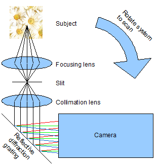
Pictured is one possible way to construct an imaging spectrophotometer. An image of a subject is focused on a slit by a focusing lens so that only a vertical stripe of the subject will be imaged. A collimation lens aligns the paths of light, so that they will land on a diffraction grating at an ideal angle. Different wavelengths are diffracted to different directions, appearing to the camera to be coming from different horizontal angles. Effectively, the camera images the complete visible spectrum of each pixel on the vertical stripe. The spectra do not overlap as they are spread horizontally on the image. The whole system can be rotated horizontally to scan the scene to form a 2D image.
A drawback with this setup is that the camera and rotation must be synchronized as the camera does not know how much the system has been rotated. This is not so easy to do well, unless the scan is made really slow (not a good thing) or the camera is electronically synchronized to rotation (hard to do and possibly expensive). Perhaps something stationary could be made visible in the lower portion of the image, to act as reference.
It appears this has been done before, for astronomy: http://www.astroman.fsnet.co.uk/needle1.htm
2009/07/08

Masking of stray light was minimal. Also, a reflective slit (a sewing needle) was substituted for the transmissive slit (made of razor blades).
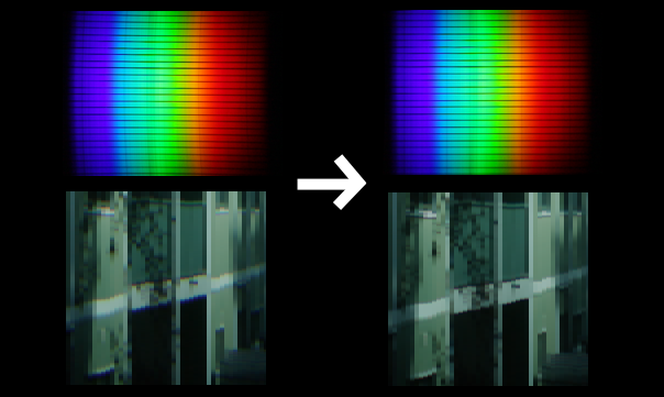
Imaged is a vertical stripe of a fluorescent lamp. The spectrum is shown spread horizontally on the reflective diffraction grating. Because the beams are not collimated, the optimal focusing distance (for the camera) varies by wavelength. Longer wavelengths (red) appear increasingly blurry, as the camera was focused on short (blue) wavelengths. Moreover, the focusing distance that gives the best horizontal resolution deviates increasingly from the vertical one for increasing wavelengths. Such optical anisotropy should also be eliminated by collimation, but at the probable cost of vignetting. Another benefit of collimation is that imperfections of the grating will be out of focus.
For parts, I bought an old Zenit EM film SLR camera from my friend for 20 EUR to obtain both the focusing lens (Helios 44M 58 mm f 1:2) and a fixture for it (the camera body). This lens has some desirable properties: manual focus and manual aperture. The diffraction grating is very large, about 8 cm x 8 cm, scavenged from some sort of a spectrophotometer, at no cost. I'm buying two more of the Zenit cameras, at ebay.co.uk, in hopes that having identical lenses simplifies the design.
2009/07/27

I bought a total of three of these. Each came with a Helios-44M 2/58 kit lens and cost at most 20 EUR a piece, including postage. The razor blade slit will rest on top of the inner film guides (the inner ones of the four bright lines), against which the film normally rests. The outer guides must go as they would otherwise lift the blades off the focusing plane.

Filing the aluminum body was easy. The inner guides were protected by multiple layers of masking tape.

This drastic operation creates some space for the focusing plate from the other camera body.

The camera bodies were mated using two wooden blocks and 8 screws, and a few spacers to correct for any inclination. The important thing is for the two lenses to share the same optical axis, and that they both draw the image on the slit (not yet installed in this picture) when focused to infinity.


Reinforcement bars keep the blades straight. Without them, the blades are too flexible and curve easily, making the effective width of the slit more dependent on viewing angle.
The width of the slit was adjusted manually while the glue was solidifying. Super glue is no good for this as it solidifies instantly.
2009/07/29

Looks promising! The image is quite sharp in both directions, and spectral resolution is awesome. Now need to worry about vignetting (darkening of the image toward corners).

This time using three Helios-44M 2/58 lenses, including one for the Canon EOS 450D camera. There's perhaps something to matched optics. The image has not even been cropped. Also, another diffraction grating is in use. Two diffraction orders are visible, and a bit of ultraviolet light from a third one. The diffraction grating is "blazed" to concentrate transmittance on the shown run of bands. That's why there are no blue bands visible on the left.
Imaged is a circuit board from a dismantled spectrophotometer. :-) The light is from a fluorescent lamp, hence the discontinuous spectrum.
Vertical resolution is satisfyingly good. The slit is perhaps too wide; some horizontal features of the imaged object are visible (not at the low resolution of this web image), especially at the narrow ultraviolet band. But this is good enough for now.
2009/07/30

The 1200 grooves/mm grating gives better spectral resolution than the 300 grooves/mm grating in the earlier picture. But also, there is not much headroom for wavelengths outside red and violet in case I get a camera that can capture a wider range of wavelengths than is visible to humans. It is possible to modify the Canon EOS 450D by removing a filter inside it, but I'm a bit scared of the process. I won't consider it before this thing is working.
These kind of gratings cost around 100 EUR a piece new, but mine were scavenged from spectrophotometers thrown away by the chemistry department, so, free.
The continuous stripe of spectrum is from the flame of a Colt cigarette lighter. :-) The background is the usual circuit board illuminated by a fluorescent lamp. There's some ghosting in the upper left corner, probably because of reflections inside the lenses. The flame was quite bright.

What the objective lens drew on the slit can later be recomposed from the spectrum. The process is illustrated. All wavelengths are simply squeezed back together. (It looks black and white, but it's the fault of jpeg image compression)
2009/09/11

Before operation, the optics are covered with pieces of black leather.

The resulting image of the first manual scanning test. The actual scan:
The video was recorded while the system was manually rotated counterclockwise. So in fact this video encodes a complete image! Points to anyone who can tell what the scene is (Joonas got some points for this!). The original resolution of each video frame from Canon EOS 450D was 848 x 560. The final vertical resolution is thus 560 pixels. With a more coarse diffraction grating, it would be possible to rotate the camera 90 degrees to get a vertical resolution of 848 pixels. The borders are just for contrast.
The image file encoding gamma 1/2.2 was taken into account. Basically, before doing arithmetic on pixel RGB values as if they were proportional to luminous intensity, they were raised to power 2.2. And before the results were written back into an image file, the inverse operation, power 1/2.2, was employed.
Still tons of things to improve in how the image is generated, but it's a good start. List of things to do:
- Correct optical distortion by postprocessing to reduce color bleeding.
- Figure out where each wavelength is.
- Take into account Canon EOS 450D RGB sensor sensitivity curves to improve dynamic range of pixels that have some of the color channels saturated.
- Replace the Canon sensor RGB sensitivity curves with CIE 1931 XYZ color matching functions to better model human color vision. (Canon ain't perfect!)
2009/08/12

A lot of extra dynamic range could be mined from this. But it needs a bit of detective work. The color space is sRGB, which is not directly the raw sensor data, but something like a linear combination including negative coefficients.
2009/08/13

Fraunhofer lines can be used for wavelength calibration. This image is for demonstration, not an actual calibration. Sandwiched is the measured spectrum of the evening sun, cut in two to increase detail in the web image. Some major and some minor Fraunhofer lines are visible.
- G, 430.8 nm, iron and calcium
- F, 486.1 nm, helium
- b4, 516.9 nm, iron
- E, 527.0 nm, iron
- D3, 587.6 nm, helium
- a, 627.7 nm, atmospheric oxygen
- C, 656.3 nm, hydrogen
There are many additional lines visible, some stronger than some of the designated ones.
Fraunhofer lines are due to absorption of light by elements in sun's outer layer and by oxygen in Earth's atmosphere.
2009/08/16

The spectrum image geometry was corrected by manually adjusting a 3x3 grid of control points and by biquadratic interpolation of the coordinates of the control points in the source image. The basis functions used were:
(0.25*x^2 -     x + 1)    * y[0] +
(-0.5*x^2 +     x)        * y[1] +
(0.25*x^2)                * y[2]
Bicubic Catmull-Rom interpolation (at gamma 1.0, of course) was used for reading the source spectrum image.
For the calibration, imaged was a black metal grid against sunlight. This provided both horizontal (metal grid) and vertical (Fraunhofer) lines that were then made straight by adjusting the control points.
The bottom row shows the resulting enhancement for the first manual scan test. Vertical color fringing is reduced.
Some types of distortion cannot be corrected by a 3x3 grid of control points, for example bulging that makes the image more dense toward the edges. So, I derived piece-wise quadratic basis functions for 4 control points. I might implement them later. Here goes:
Left block, x = 0..1:
(0.25*x^2 - x + 1) * y[0] + (-0.5*x^2 + x) * y[1] + 0.25*x^2 * y[2]
Middle block, x = 0..1 (for convenience, instead of x = 1..2):
(0.25*x^2 - 0.5*x + 0.25) * y[0] + (-0.25*x^2 + 0.5) * y[1] + (-0.25*x^2 + 0.5*x + 0.25) * y[2] + 0.25*x^2 * y[3]
Right block, x = 0..1 (for convenience, instead of x = 3..4):
(0.25*x^2 - 0.5*x + 0.25) * y[1] + (-0.5*x^2 + 0.5) * y[2] + (0.25*x^2 + 0.5*x + 0.25) * y[3]

Because the sensitivity curves of the Canon sensors were unknown, the readings needed to be normalized against a light source of a known spectrum. The emission spectrum of an incandescent lamp is very close to black-body radiation, which is well characterized theoretically. I happened to have a 10.8 V 30 W halogen bulb from a spectrophotometer, unfortunately of unknown color temperature. But it was possible to measure the color temperature against the white balance settings of Canon EOS 450D. I hooked the lamp to a 12 V power supply and filtered the power further by a large capacitor (on the right in the picture). I allowed the lamp to heat up for a few minutes and took a picture of it without a lens using the incandescent white balance setting, "approximately 3200 K", as reported by Canon. The picture was basically a gray rectangle.
The average color in the rectangle was sRGB 152, 144, 143. In linear sRGB (gamma 1.0), this is 0.3140, 0.2789, 0.2747. The CIE1931 xy hue for 3200 K black-body radiation is 0.4234, 0.3990, which is equivalent to linear sRGB 0.6703, 0.3456, 0.1299. That multiplied with the lamp's linear sRGB color gives the color of the lamp using the correct sRGB reference white point of 6500 K. The result is in linear sRGB 0.2105, 0.09637, 0.03567, or in xy 0.4352, 0.3962. This does not correspond exactly to black-body radiation at any temperature, but comes closest to 3100 K, for which xy is 0.4300, 0.4016.
To summarize, it could now be presumed that the lamp emits black-body radiation at temperature 3100 K, or 2800 °C for those who wonder.
2009/08/21
I found the specificationss of the lamp, and surprise, surprise, a color temperature of 3100 K was cited. :) I'm using a somewhat higher voltage, 12 V instead of the specified 10.8 V, so the true color temperature will be somewhat higher.
2009/08/24

To rotate the spectrophotometer I needed a really slow-revolving motor. I was first thinking of stepper motors, but digging into my piles of stored junk I found four Maxon DC motors (about 12 V) with 5:1 gearheads. Better yet, the gearheads could be detached from the motors and, put in a suitable configuration, chained. Four gearheads in a chain gives a total gear ratio of 625:1.

I drilled flat-bottom slots for the gearheads into 2-by-4 lumber. A couple of attempts failed because some of the slots turned out slightly misaligned.
My plans were: Slot diameter is 35 mm. The depth of the first slot (the one with the motor) is 14 mm. Successive slots ascend 6 mm per slot. The slot chain turns 60° counterclockwise at each slot, successive slots being separated by 30.5 mm center-to-center. Gearhead output shaft hole diameter is 12 mm and is 7 mm off the slot axis, oriented straight towards the next slot in the chain.

Following my original plans, the distance between gearheads had to be accurate down to about 0.3 mm. This was hard to achieve. As a trick to get around this problem, positioning errors were compensated for by rotating the gearheads and by changing the chain turning angle accordingly. A slot was drilled for just one gearhead at a time, the gearhead was rotated in the slot until the gear teeth meshed correctly with the previous gearhead, and the chain was continued to the direction pointed to by the orientation of the gearhead. Done this way, and with a bit of luck with the holes for the gearhead output shafts, everything worked on first go.
The gearbox was later sawed off, sanded slightly, cleaned and spray-painted to fixate wood dust and splinters to keep the gears clean.

The belt drive will further increase the gear ratio from 625:1.
2008/08/25
Running the motor at 12 V, I clocked 1 min 18 s per revolution of the transmission output shaft. For the motor, that is 8 revolutions per second, 480 rpm.
2008/08/26

I tried the belt drive mechanism but it resulted in jerky motion. This is my theory why: Slow rotation combined with the elastic rubber belt and friction of the turntable plate shaft allows the plate rotation to halt repeatedly. During such a halt, tension of the belt builds up until it is stronger than the static friction of the plate shaft, yanking the plate back into rotation. The rotation speed of the plate temporarily exceeds its average rotation speed, causing the belt to loosen. This gives another opportunity for a halt. There wasn't much to do to reduce plate shaft friction. I tried oiling it, helped none.
There was so much weight on the plate that significant friction resulted in any case. So, something had to be done to the elasticity of the rubber belt. The solution was a roller mechanism. The belt was removed, and an O-ring was slipped around the gearbox output pulley which was then pressed against the turntable plate pulley (the shiny, curved metal strip in the image). This resulted in smooth and steady rotation of the turntable plate.

Inside the case there is a cavity that contains 3 x 3.7 V lithium ion cells in series totaling 11.1 V. The case has a 12 V DC power input and a switch that enables the batteries for charging or for use. I don't know how smart that was; now the motor will be running when batteries are charging. Perhaps the sound is a good reminder not to forget to disconnect power
On the gearbox, there is a switch for changing the direction of rotation. The motor can actually be disconnected by setting this switch in the middle position. The switch does not lock in the middle position, so that way of stopping the motor is a bit cumbersome and unreliable. The batteries will rarely need charging, so perhaps I won't add an extra switch for turning off the motor.
A furniture hinge with a spring connects to the gearbox. The spring ensures that the roller is pressed with enough pressure against the turntable plate pulley. The plate is not installed in this picture.
Running on batteries, I measured one complete turn of the turntable plate taking 8 min 59 s. Given the Canon EOS 450D frame rate of about 20.7 frames per second (using the longest exposure), one gets about 11000 pixels per rotation. For comparison, a 50 mm focal length lens, which is often said to give a natural viewing angle, gives a horizontal viewing angle of 39.6° on a 35 mm camera body. This system would have a scanned horizontal resolution of about 1200 pixels for that viewing angle. Sounds good to me.
The motor and batteries do not heat noticeably even if the motor is left running for a long time. Guess the motor does not need to generate much torque. Even with the turntable plate installed, the motor was running happily on batteries for 5 hours, or until I stopped the test.

Each Zenit EM camera came with a case, each of which had a metal part with the standard thread for connecting to a camera stand. One such part was embedded and immobilized into the bottom of the support case, in line with the turntable shaft.
2009/08/28

With motorized scanning, horizontal resolution is at least on par with vertical resolution. This image is at the original resolution.
One worrisome thing is that sensor noise is starting to be visible if gain is increased any further. This applies when there is not enough light, like on a cloudy day as in this picture. Most of the noise appears on the red channel. Here in Finland, it is getting darker and darker as we go further into autumn, so I'm afraid I won't get much outdoor images in near future.
A good thing is that as the rotation is so smooth, there is no need to synchronize the camera to rotation. Frame dropouts are still possible though.
I was thinking about buying a Philips Living Colour ambient-lighting system. Though it’s mere a single lamp, not system-system. I was then thinkin, after I read this blog entry of yours, could it be possible to use that very same method of splitting the spectrum out of visible light to fill whole room with rainbow’s colors? Like placing a prism between the beam of sunlight but with more scattering result (ie. thru lenses or so) ?
Also I’m happy to see you have this blog, it’s nice to see someone so talented sharing his wisdom :)
Ruottis,
If you want to split the light into rainbow colors that illuminate the walls of the room, then the problem is two-part: Firstly, you need a continuous-spectrum light source that projects a stripe of light on the wall (this would then be spread out into a rainbow). The easiest would be a transparency projector with a mask that has a hole the shape of a stripe. But the mask is going to absorb a lot of the light. So a lens system would be better. Now what is required from such a lens system? Well, “a stripe” is compact in one dimension and spread-out in the other. So you need a cylindrical lens or a mirror instead of a spherical one that acts the same in both dimensions. Like a transparent bottle filled with transparent liquid, or a polished piece of metal that is bent into “U” shape. Secondly, you should use a diffraction grating to spread out the spectrum. Diffraction gratings are no more than four or so centimeters in width, so this means that at some point, all the light should flow through an area of such a small size. That’s where you’d put the grating. Additional lenses may be required for all this.
I found this patent that describes something similar, but using a prism instead of a diffraction grating: http://www.freepatentsonline.com/4557055.pdf
i decoded your youtube video! :) fetching it with the great youtube-dl script, and splitting it into frames using ffmpeg, the following lines of python (using IPython –pylab or numpy/matplotlib) did the trick:
imm = zeros([480,391,3])
for i in range(1,391):
im = imread(‘frame%04d.jpg’ % i)
imm[:,i,:] = sum(im, axis=1)
imshow((imm[::-1,::-1,:]/imm.max())**(.45),extent=(0,848,0,560))
Hope that code came out ok.
(btw thanks a LOAD for your DSP Tut for the Braindead, it helped me greatly with my first steps into DSP for writing the softsynth for my 4k demos, 13 years ago)
Good job Ritz! :D That seems so simple the way you put it. I’m still waiting for a cheap full-frame video camera (that doesn’t decimate the pixels) to appear before continuing this project.
I wonder… a possible improvement for the poor sensitivity (and also spectral / vertical resolution, if not horizontal). Instead of using video mode, what about burst mode or timelapse still image capture? Particularly under automated external control, or if there’s a suitable option either in the EOS’s OEM menus, or if there’s a custom firmware available for it much like CHDK for the Canon A720/etc prosumer pocket digicams? Even if you only extend the exposure time to 1/30th of a second that may improve the amount of light captured by at least 2 to 4 times (depending on framerate and what the effective shutter “angle” is, usually no greater than 180 degrees), as well as greatly increasing the resolution (which lets you increase the gain by downsampling to an intermediate resolution using an additive, rather than averaging filter).
There might then be a need for some further engineering on the turntable side to make it turn more like a very fast running second-hand on a clock (or the 1/10ths hand on a mechanical stopwatch, or more relevantly the shutter of an old movie camera/projector), synchronised to the camera exposure so it only moves when a picture isn’t being taken and is still during active exposure, so a sweep can be completed in a reasonable amount of time without blurring (though, the worst you’d see without that would be equivalent to a 1-pixel horizontal motion blur, so it might be thought worthwhile for ease of engineering), but it would be worth it to improve the light capture.
Tahrey: I now have much better cameras with raw video capabilities. I just need to pick up this project again. I think the 1-pixel horizontal motion blur is fine. It’s not going to affect light capture. It would be quite impossible to have a high resolution with “jagged rotation”.