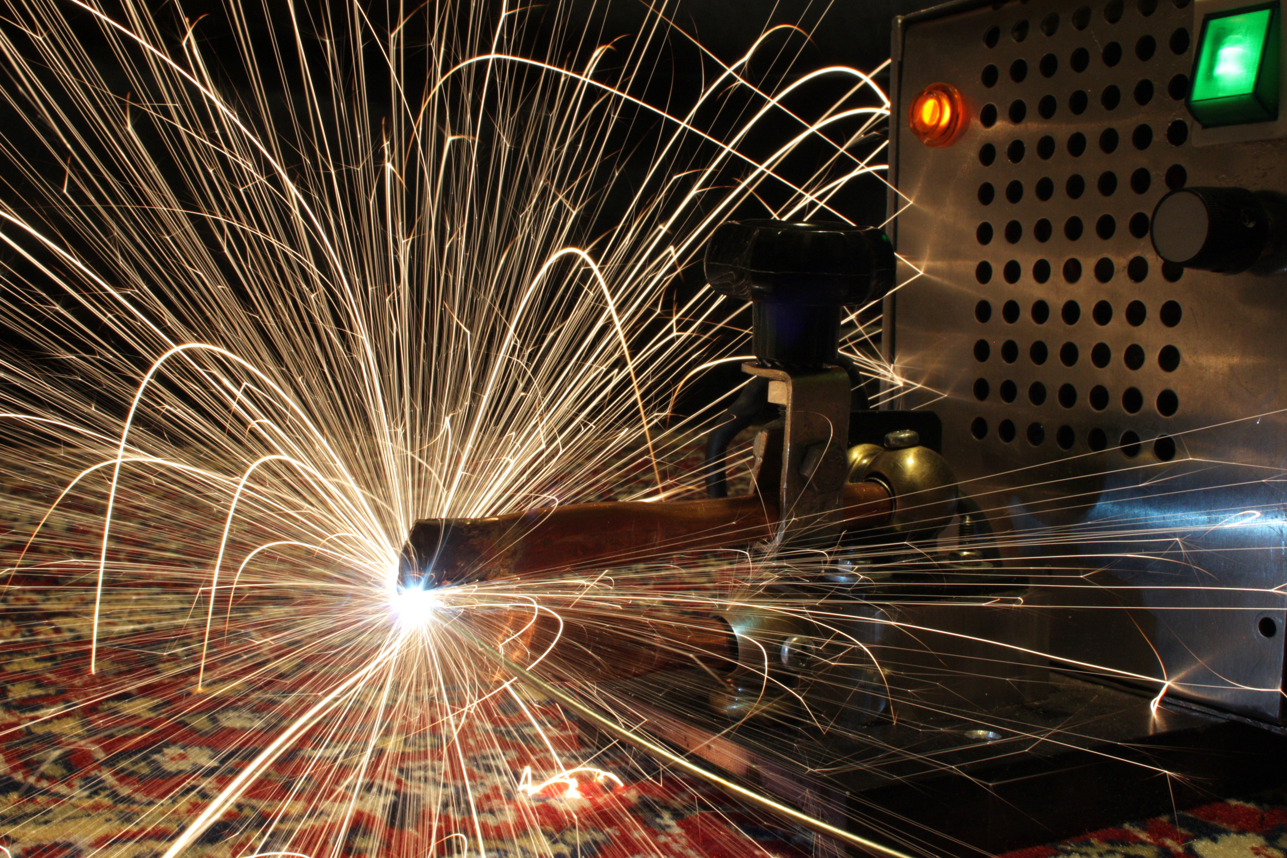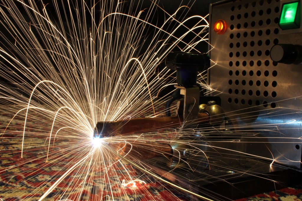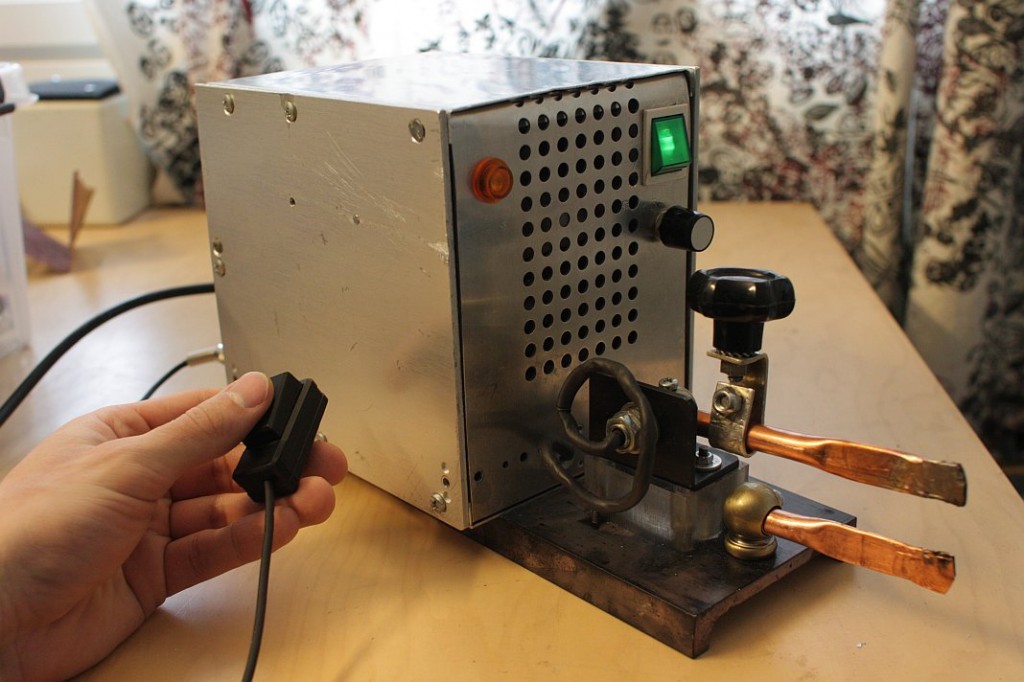
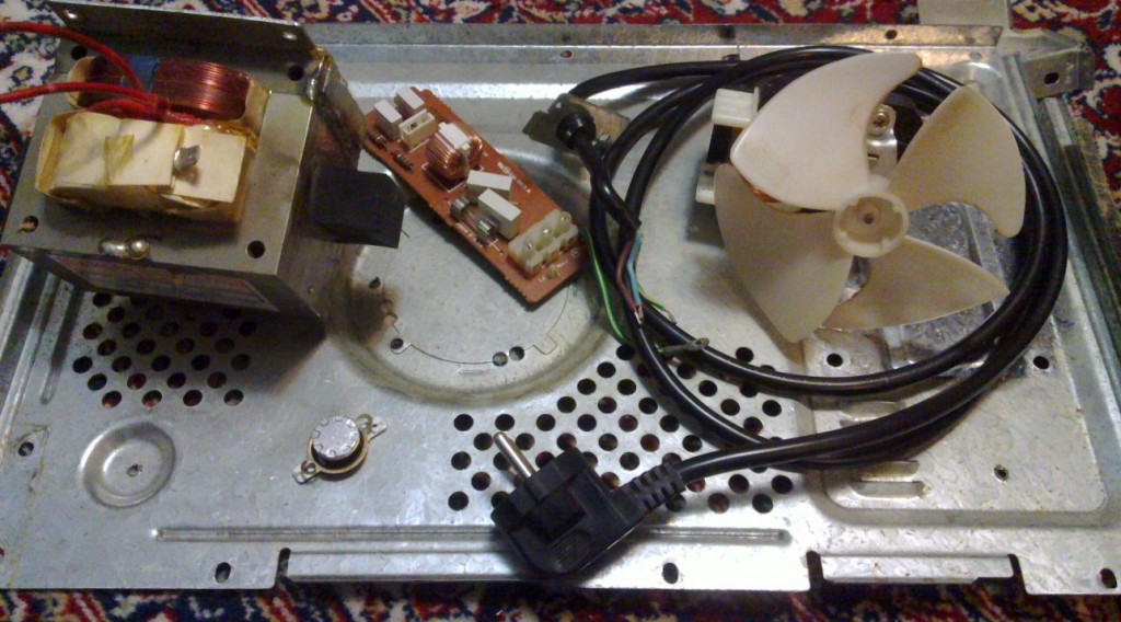
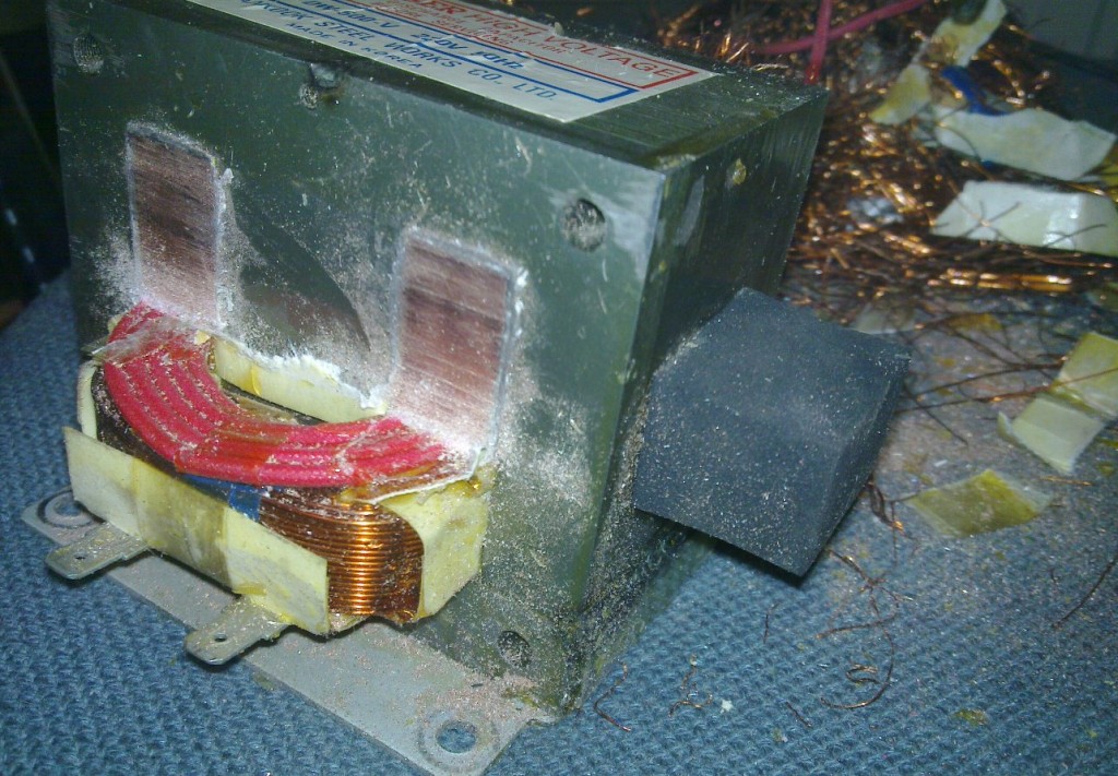
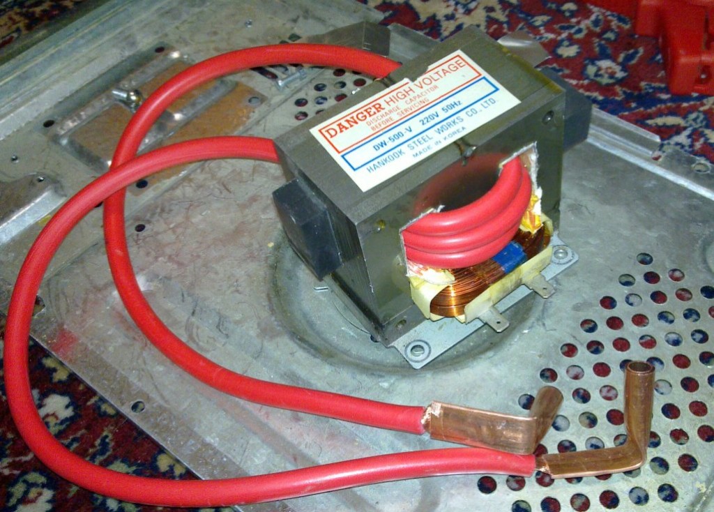
I made a spot welder out of a microwave oven transformer and a starter cable. Those are quite popular actually. They use a solid state relay to switch the transformer on and off. I use a Fotek SSR-40DA DC-controlled 40 A AC-zero-crossing-switching solid state relay. It was only 4 € and free shipping on eBay. First I needed to extract the transformer from a microwave oven and to replace the secondary coil with a starter cable.

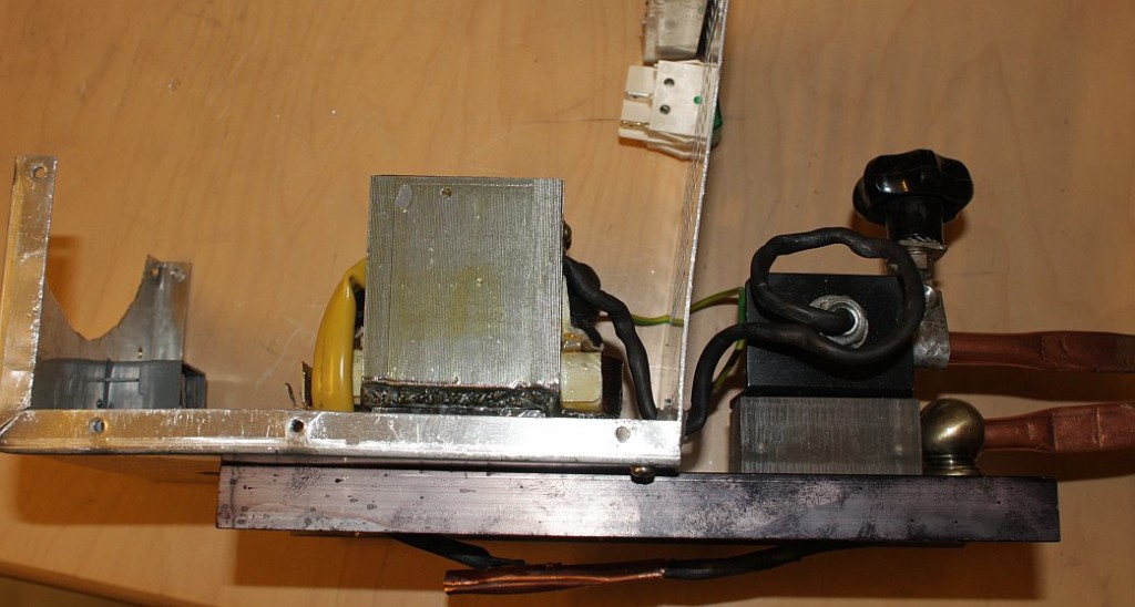

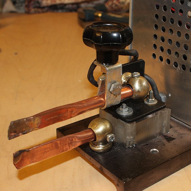
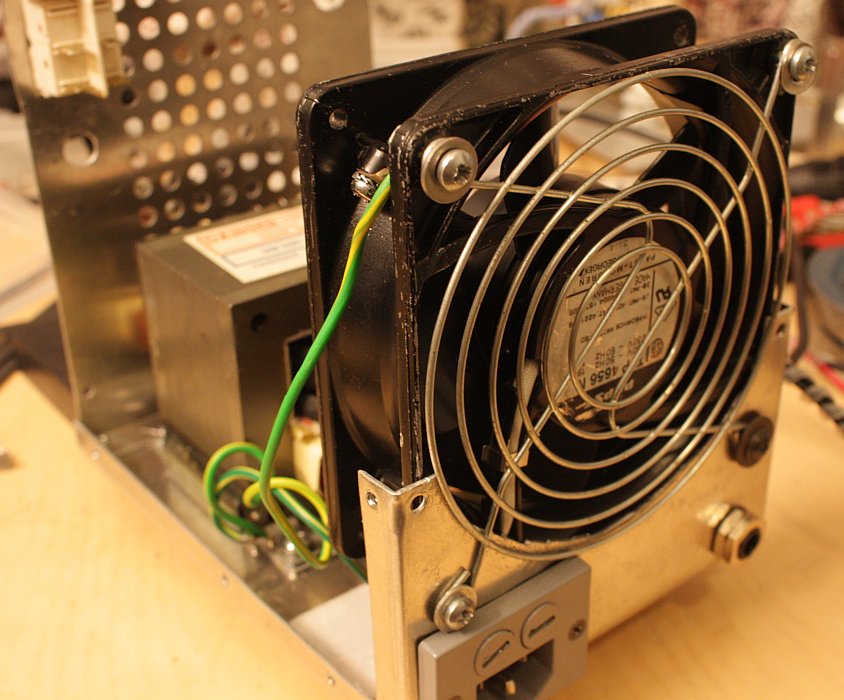
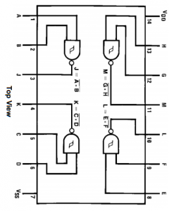
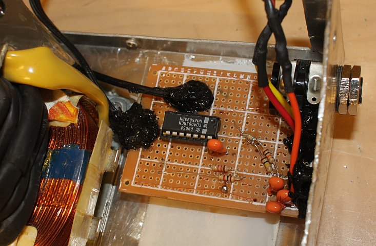
I wanted to automate the welding timing so I made this simple adjustable-duration pulse generator circuit out of some components that I had around:
|
|
Parts list:
- Resistor 1 kohm (R4)
- Resistor 9 kohm (R1)
- Resistor 40 kohm (R2)
- Multi-turn or log taper pot 10 kohm (VR1)
- 3x Capacitor 10 V 10 uF (you can put the extra capacitor in parallel with C2 to make the pulse longer if needed) (C1, C2)
- CD4093BC Quad two-input NAND Schmitt trigger logic gate
The variable resistor VR1 controls the timing. I used a helical potentiometer but a log pot would probably work just as well. The higher resolution is needed for long welding pulse times for which the whisker of VR1 is close to R2. R1 and R2 adjust the range of the voltage divider. Capacitor C2 is also charged through R1. The voltage divider range should be such that at one extreme, continuous welding is just barely enabled (by keeping the button pressed), and the other extreme just barely gives the shortest welding time that may be needed. If the obtainable shortest welding times are unnecessarily long, the capacitor C2 can be made larger. This will make it easier to get also very long pulse times. Doubling the capacitance should double the timing.
A rough approximation on how the voltage across C2 rises after the button is depressed at time $t = 0$ is given by:
$V_{\text{C2}}= \frac{5\text{V}\cdot t\cdot(R_{\text{R2}} + R_{\text{VR1}})}{C_{\text{C2}}\cdot R_{\text{R1}}\cdot(R_{\text{R2}} + R_{\text{VR1}}) + t\cdot(R_{\text{R1}} + R_{\text{R2}} + R_{\text{VR1}})}$
where $R$ is resistance and $C$ is capacitance across a component. $R_{\text{VR1}}$ is the nominal resistance of the variable resistor, not the current set value. The first half of the variable resistor VR1 and the second half of the variable resistor VR1 + resistor R2 act as a voltage divider that feeds a divided $V_{\text{C2}}$ to a Schmitt trigger which will trigger at nominally 3.3 V, ending the pulse.

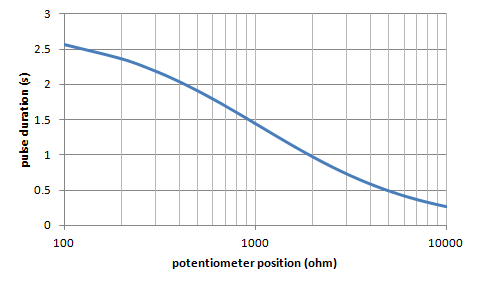
An initial version of the circuit took about a second to recover before it was able to produce another pulse after releasing the button. Resistor R4 was added to remedy this. It quickly drains the capacitors empty when the button disconnects the circuit from the power supply.
The circuit is fail-safe in the sense that it only gets power through the button. If the button is released, the output soon goes down, even if the IC or anything else in the circuit malfunctions for some reason. I use this circuit to control (the LED + series resistor of) an optically isolating solid state relay directly.
Noise can be a problem at longer pulse durations, where a sudden spike may end the welding pulse prematurely.
The timer is not synchronized to AC, so timing will also vary if the solid state relay is of the zero-crossing switching type.
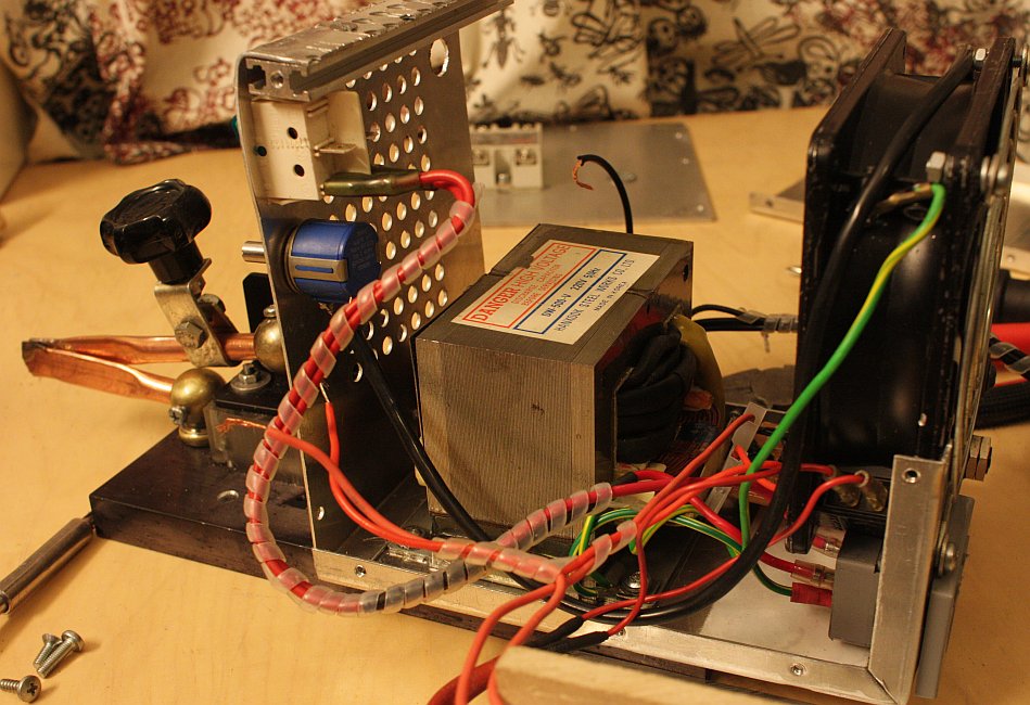
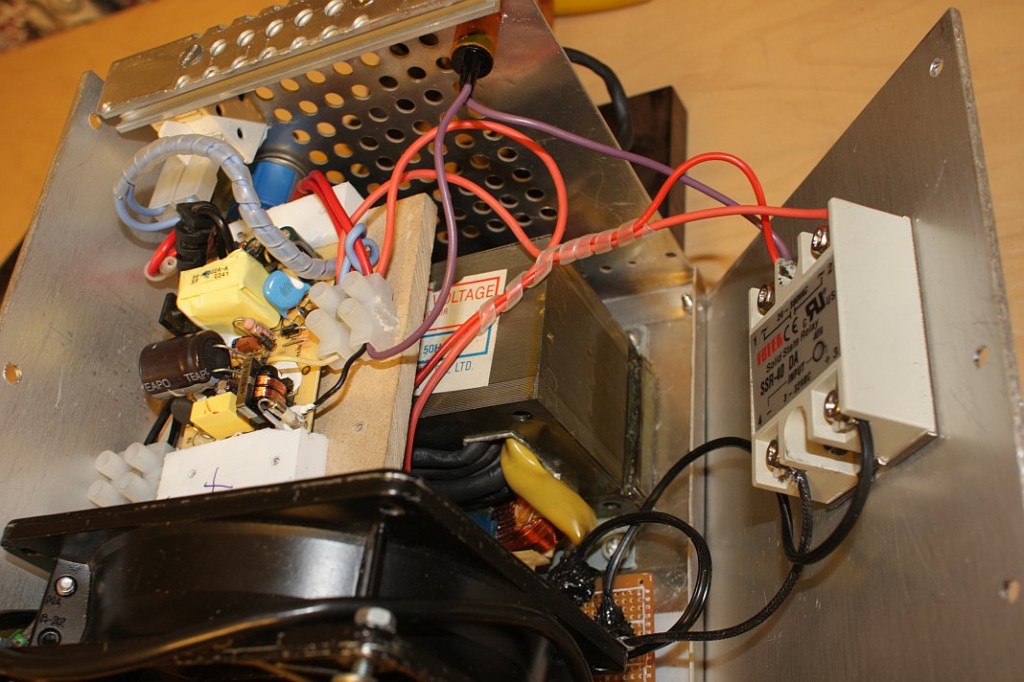

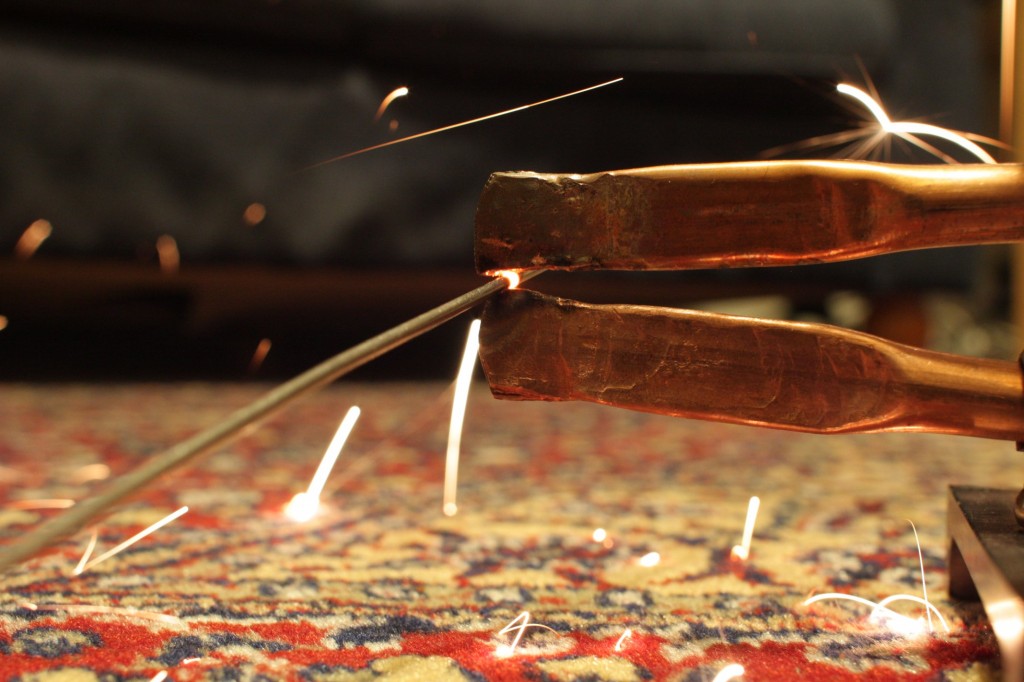
Welding results are mediocre at best. But strong enough for some purposes. One problem is that when the workpiece starts to melt, the current increases dramatically, causing a small "explosion". I am not sure how this could be improved upon to give a steady current.
