2011-10-25
I found from a dumpster a Hyundai L17T LCD TV, pretty much a monitor with an analog TV tuner. I tried to turn it on, but the power indicator light was simply flickering slowly, indicating a short circuit somewhere. Nothing on the screen. The monitor was trying to power up, but then a fail safe switched it back off. And the cycle repeated.

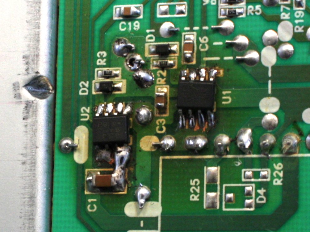
I opened the monitor and saw that the circuit board had darkened around two components, identified as FDS8958A dual N & P-channel PowerTrench MOSFET's. A darkened circuit board should mean heat, and heat is an indicator of component failure. Solder around the components also looked a bit jagged, probably as a result of a cycle of melting and solidification. I could recognize that part of the circuit as the inverter power supply for the fluorescent backlight lamps. I scratched away the circuit trace that supplied power to the inverter, to see if the monitor would turn on without the backlight:

The monitor turned on without problems this time, and I could see a faint picture on the dark screen. In hope that it was just the power transistors that had failed, and that the rest of the inverter circuit was still OK, I looked for replacement components from my collection of electronics junk. Thanks to a hint from my brother Veli-Matti, I could find identically specified components from an old main board:

The suitable components on the main board were AP5401 N and P-channel enhancement mode power MOSFET's. I carefully removed two of them from the main board, and replaced the inverter power transistors with them:

I didn't save on the solder, because I thought the transistors might benefit from a bit of heat sinking. After the repair, the monitor worked as good as new. Another piece of trash less in the world! I didn't have time to take a picture of the working monitor (or the broken one), so here is one fished from Internet to your satisfaction:

The following day the monitor left my disposal to be slowly on its way to Gambia where my friends at Apu-Paku Ry are going to build a music recording studio, among other great things that they will be doing.
I can’t even get the back off the monitor!!
The power switch is very intermittent – now it won’t power up at all!?
Thanks
Alan, sorry, can’t remember exactly how to open it. Generally: Remove all screws, look for locking buttons and hidden screws, then pry (with screwdriver if necessary, it’s not an expensive monitor).
I guess not. I have an monitor LG L1730S, was burnded same chip FDS… I changed it, it worked around 20 mins and then again black. actualy I see a picture first when I open it but in 1/10 of secont become black again. Caps seems ok. I cant find any other short circuit anywhere. and teh other same chip FDS… looks ok and acording with my multimeter is not shorted !
What else can have?
Baios, I don’t have too many ideas. But does the monitor switch off or is it just the lamps that turn off? If just the lamps then there should still be a very very faint picture on the monitor. If it’s the monitor that turns off then maybe try what I did, cut the trace that gives power to the inverter (you can repair the trace later). If the monitor then stays on then it’s probably still a short circuit in the inverter. Could be even your replacement transistor. There might be some useful info here for you: http://neoxy-yx.blogspot.com/2011/12/tips-and-tricks-on-repairing-lcd.html
Hello
I could you clarify a question I have? … Is that I see you’ve welded pins 1 and 2 each right?
and 3 and 4 each component before welding to c1?
thanks
Toni, I made no new connections. Those pins were already connected together through the copper but I just added a lot of solder because I had damaged the copper somewhat when removing the burned chips.
I wanted to ask why the sound is gone to me sometimes appears on the monitor. Hyundai L17T model
Sorry, no idea!