This is probably the most efficient structure for implementing a Hilbert transform. Actually, it's not a Hilbert transform, but two all-pass IIR filters whose phase difference is approximately 90 degrees over a range of frequencies symmetric around Nyquist/2. Laurent de Soras uses these kind of filters in his HIIR resampling library, which also has functions for coefficient calculation. This note is available in Maple format: hilbert.mws UPDATE 2019-06-28: See my Signal Processing Stack Exchange post for coefficient calculation using HIIR.
90 degree phase difference IIR allpass pair
> H_sect := (z, a) -> (a^2 - z^(-2)) / (1 - a^2 * z^(-2));
![[Maple Math]](http://yehar.com/blog/wp-content/uploads/2009/09/hilbert1.gif)
Equation 1. Allpass section taking one multiplication when a^2 is a known coefficient.
Each such allpass section has poles located on the real axis at a and - a , and zeros at 1/ a and -1/ a .
We construct two allpass filters from such sections:
> H_1 := z -> H_sect(z, 0.6923878)*H_sect(z, 0.9360654322959)*H_sect(z, 0.9882295226860)*H_sect(z, 0.9987488452737)*z^(-1);
Equation 2. First allpass filter, delayed by one sample.
> H_2 := z -> H_sect(z, 0.4021921162426)*H_sect(z, 0.8561710882420)*H_sect(z, 0.9722909545651)*H_sect(z, 0.9952884791278);
Equation 3. Second allpass filter, has 90 (+- 0.7) degrees relative phase to first filter over a long range of frequencies.
> plot({argument(H_1(exp(I*freq))), argument(H_2(exp(I*freq)))}, freq=0..Pi, phase = -Pi..Pi);

Figure 1. Phases of H_1 (green) and H_2 (red).
> plot(argument(H_2(exp(I*freq))/H_1(exp(I*freq))), freq=0..Pi, phase = -Pi..Pi);
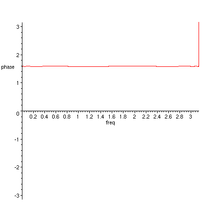
Figure 2. Phase difference of H_2 and H_1.
> plot({argument(H_2(exp(I*freq))/H_1(exp(I*freq))), Pi/2}, freq=0..Pi, phase = Pi/2*0.95..Pi/2*1.05);
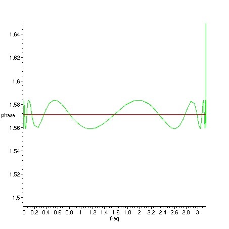
Figure 3. Phase difference of H_2 and H_1 (green), detail near 90 degrees (red).
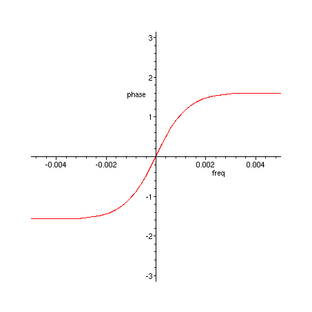
> plot(argument(H_2(exp(I*freq))/H_1(exp(I*freq))), freq=-0.005..0.005, phase = -Pi..Pi);

Figure 4. Phase difference of H_2 and H_1, detail near 0 Hz.
You can use the 90 degree phase difference of the filters as such, or you can construct a complex filter and analyze its properties:
> H := z -> 0.5*(H_2(z)+I*H_1(z));
Equation 4. Combined complex filter that will remove negative frequencies.
> plot(20*log10(abs(H(exp(I*freq)))), freq=-Pi..Pi, dB=-60..1, axes=boxed);
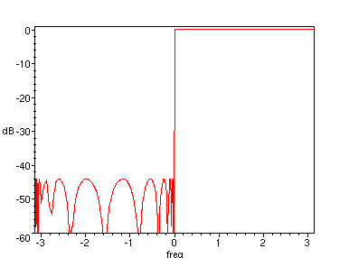
Figure 5. Frequency response of filter in Equation 4.
> plot(20*log10(abs(H(exp(I*freq), 0.4))), freq=-0.01..0.01, dB=-60..1);
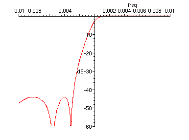
Figure 6. Frequency response of filter in Equation 4, transition band detail
> plot(20*log10(abs(H(exp(I*freq), 0.4))), freq=0..0.01, dB=-0.0005..0.0005);
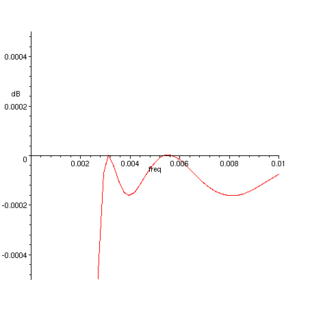
Figure 7. Frequency response of filter in Equation 4, transition band - passband detail.
> plot(20*log10(abs(H(exp(I*freq)))), freq=0..Pi, magnitude=-0.0005..0.0005);
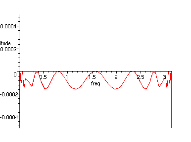
Figure 8. Frequency response of filter in Equation 4, passband detail
Transition bandwidth is 0.002 times the width of passband, stopband is attenuated down to -44 dB and passband ripple is 0.0002 dB.
Plenty cheap for a total of 8 multiplications (plus final scaling by 0.5)!
The coefficients were found using a generic evolutionary algorithm. I believe that it would be possible to design coefficients for this filter structure using the software by Artur Krukowski, which finds coefficients for halfband filters: http://www.cmsa.wmin.ac.uk/~artur/Poly.html
Update 2004/01/13
Ben Saucer has succesfully implemented this filter pair to be used in his audio effect. Here are some useful (edited) excerpts from our e-mail correspondence.
Here's a quick diagram of the allpass pair:
        ................ filter 1 .................
   +--> allpass --> allpass --> allpass --> allpass --> delay --> out1
   |
  in
   |    ................ filter 2 .................
   +--> allpass --> allpass --> allpass --> allpass ------------> out2 (+90 deg)
We can use cookbook formulas to convert an allpass section into code. A general IIR recurrence relation:
  out(t) = a0*in(t) + a1*in(t-1) + a2*in(t-2) + ...
         + b1*out(t-1) + b2*out(t-2) + ...
results in the transfer function:
         a0 + a1*z^-1 + a2*z^-2 + ...
  H(z) = ----------------------------
          1 - b1*z^-1 - b2*z^-2 - ...
The allpass section in question has the following transfer function:
          a^2 - z^-2
  H(z) = ------------
         1 - a^2 z^-2
We want to convert this into the recurrence relation. According to the cookbook formulas and the above transfer function:
  a0 = a^2, a2 = -1, b2 = a^2, rest of coefficients zero

  =>  out(t) = a^2*in(t) - in(t-2) + a^2*out(t-2)
which simplifies to the one-multiplication allpass section:
out(t) = a^2*(in(t) + out(t-2)) - in(t-2)