I encountered a treasure trove of old Bruel & Kjaer gear at a military surplus store, and bought everything (with affordable prices):
- Bruel & Kjaer 2804 microphone power supplies with BNC output adapters.
- Bruel & Kjaer 4144 1" condenser microphone capsules with protection grid.
- Bruel & Kjaer UA 0135 silica gel drying caps for 1" microphones.
- Bruel & Kjaer DB 0375 adapters for 1" microphone and 1/2" preamp.
- Bruel & Kjaer 2619 preamplifiers.
The power supplies had leaked alkaline batteries in them and had some corrosion and moisture damage. I restored a couple of the power supplies into good working condition, and the rest I might do something more experimental with. I'm not so much interested in measurements, more in music and audio recording. The microphones and preamps seem very low-noise and are oozing of high construction quality.
Bruel & Kjaer 2804 microphone power supply
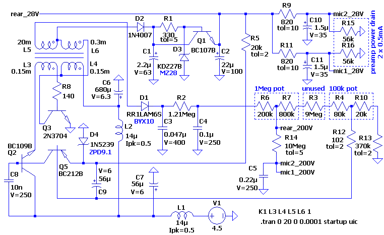
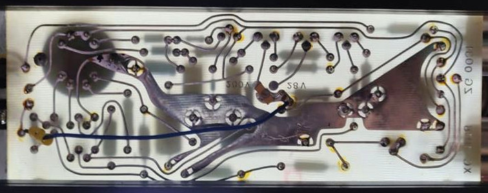
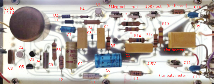
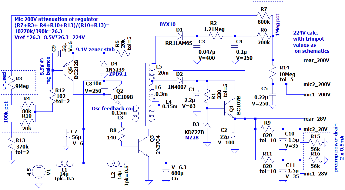
The following is my reverse-engineered schematic of Bruel & Kjaer 2804 microphone power supply. If no spice model is available for a component, the original name is given in blue and the replacement in black text. The condenser microphone polarization voltage was set to 200 V DC by a jumper on the circuit board. I did not explicitly include individual resistors and the potentiometer for the unused 28 V DC polarization voltage. LTspice source file: 2804. 2804 circuit board vertically flipped bottom, circuit board top, and two versions of a slightly simplified schematic (the latter one has been reorganized to be in a more standard way by Paavo Niemitalo):

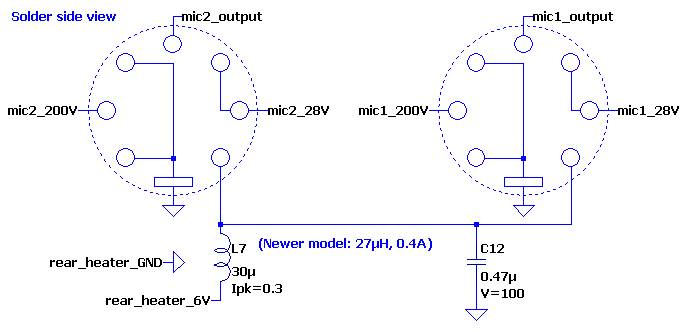
The microphone preamp connectors are soldered to the above circuit and to the outputs (via the selector that can swap outputs 1 and 2) like this: (LTspice source: bk2804_mic_conn.asc)
This is my understanding of the circuit functions: Primary side and transformer:
- V1 represents 3 x 1.5 V batteries in series. A front panel switch disconnects battery negative from ground.
- L1, C7 protect the device from current spikes and provide some input power filtering.
- Q2 controls current to oscillator.
- Q3 works as an oscillator together with the surrounding passive components.
- L3, L4, L5, L6 are coils in a transformer with possibly badly guessed inductance values. I did measure the series DC resistances and figured the coil arrangement based on those.
28 V DC microphone power supply:
- D2 is a rectifier diode.
- C1 filters the rectified current.
- D3 is a 28 V (27 V if substituted) voltage regulator diode assisted by Q1.
- C2 filters the output voltage.
- R9, R11 limit current to individual microphone preamplifiers.
- C10, C11 filter the power to individual microphone preamplifiers and provide channel separation.
- R15, R16 represent the power drain of individual Bruel & Kjaer 2619 microphone preamplifiers.
200 V DC microphone polarization voltage supply:
- D1 is a rectifier diode.
- C3, R2, C4 filter the unregulated 200 V.
- R6, R7 represent a potentiometer for finely adjusting the polarization voltage.
- R14 limits the flow of the polarization current to the microphones.
- C5 filters the polarization voltage and provides channel separation.
- Q5 compares 8.4 V (adjustable ±1 V) which is resistor-divided from 200 V DC, to a 9.1 V reference voltage generated by D4 from the 28 V DC supply. The base-emitter turn on voltage of Q5 is -0.62 V, so it is effectively comparing 8.4 V to a 8.47 V reference voltage.
- Q2 is controlled by Q5, reducing or stopping current to the oscillator if the nominal 200 V DC is approached or exceeded. This reduces current through the rectifiers D1, D2. There is much more headroom for the regulated 28 V DC power supply behind D2, so it is not affected (unless something draws too much 28 V DC) whereas 200 V DC gets regulated.
- L2, L4, L6, L5 allow current to flow from the battery to the 28 V DC and 200 V DC supplies when the device is starting. This eventually turns on the oscillator by the comparator described above.
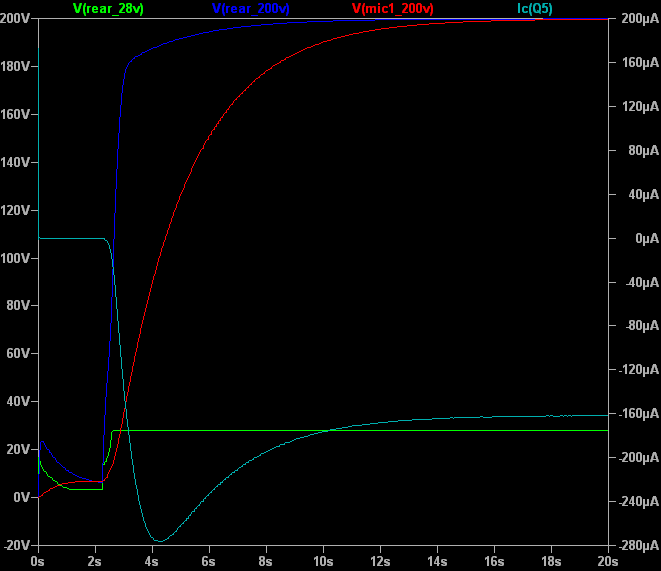
The above shows how the power supply starts and how the voltages settle. The collector current of Q5 is also monitored, because it controls current to the oscillator.
The transformer is by Siemens, with markings 651 T26, M 01, OL, indicating a size of 18x11 (mm?), that the material is SIFERRIT type T26, there is no gap (Ohne Lücke). Enameled wire coils are wound very neatly and the transformer has been dipped in perhaps beeswax. Pins 6, 7 are unused and an unrelated trace has been routed through them.